The good part of the whole engine bedding installation was presence of an old shaft. Apart from that there was an empty space to be prepared for an inboard engine. On the margin note: I never done it before and almost every element of it was a challenge.

After some research, taking measurements and lot of thinking I begin with initial cuts and fitting small shelve to support a water lock.

The idea was to find the best location for all system fittings and have them in place first, including seacock for engine water cooling. I found very useful and inspiring two websites: Corribee.org (engine) and Pbase.com (seacock) as well as other websites and pictures of engine installations I could find on-line.
Luckily, there was an old shaft with an outboard?!? propeller and a stern tube with stuffing box but it was a good starting point. Here is a picture of how it was and is now:

In the meantime new shaft with 12″/9″ pitch propeller and rope cutter was ordered as well as coupling. The latest was another issue to be resolved. Because I found the Aquadrive on CoxEngineering (also fitted on Corribee) it was strongly considered but limited and narrow space where shaft is fitted and the need to move the engine further forward I decided on Centaflex CF-M-127-K-2-2-20.
Having shaft with coupling in place I made an engine template or jig allowing for accurate measurements and alignment for bedding. It was cut from 18mm play. To make it lighter I cut holes on each side of it. The top side of it was at the level where engine feet would come. All dimensions for the jig were taken from Yanmar 1GM10 drawing.

As you can see on the above picture, the battery tray, water lock and water strainer were fitted. Now, it was time for the bedding itself. I choose the easiest route, that is marine play and hard wood. It crossed my mind to make it as a fibreglass mould and maybe it would make sense but amount of work required and time on this put me away. Simply it was easier to cut 12mm play, slightly bigger, to make sides and use hard wood for the centre part where the engine feet will be bolted to. So I did just that. The jig came as the perfect tool for positioning and bonding. Also, further cutting was necessary to make access for fibreglassing.

To sit in place each side of the bedding I used made by East Coast Fibreglass Crystic compound and to make easy bolting engine feet I used big head bonding nuts epoxied to bottom of each central part of the bedding sides.
Bedding is now bonded and fibreglassed.

One of the side jobs was to fit a fuel tank, fit a fuel filter, run fuel hoses and wires from a fuel sender (not provided with the tank).
It was another small challenge. The plastic it is made of is kind of slippery, the port side locker has an awkward shape, so some supporting fitting was needed. Also, it is not possible to put the tank I have through the opening in the locker, so I cut a bigger hole in the bulkhead. Bigger, because it was used by previous owner to slid-in the gas bottle into the locker (not the best idea as the locker is connected to the cabin and bilges).

This tank is made by Osculati, has big inspection hatch (can be unscrewed for tank cleaning) where fuel lines are connected and where the fuel sender can be fitted. There is also an optional but blanked opening with 1/2″ BSP thread for fuel return feed, which is needed but it was quite a task to find 90 degree, male 1/2″ BSP with 6 mm hose tail. This diameter is on Yanmar’s fuel return. I used 8mm as the only I could get. On the picture below you can see fuel sender already fitted and fuel line connected.

After some tweaking fuell tank was properly fitted and secured with two strips.
The next step was to paint the engine bay with new bedding and … put the Yanmar in! As you can see in the picture I added supporting ‘slabs’ on each side of the bedding to prevent eventual tendency to move sideways and add strength to the structure.

So, the Yanmar is beautifully fitting in.
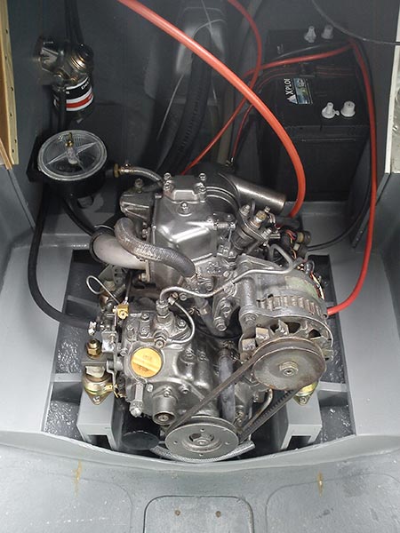
Of course, it needed be fully connected and wired. There was no remote shaft greaser in place as well as control panel had no its own location yet. The anti-syphon had to be fitted too because the engine exhaust is below the water line. Also, I didn’t mentioned the engine control lever but it was fitted on the starboard side, which can be seen on the picture with the tank viewed through the bulkhead.
To keep this page shorter the chapter on building engine housing has its own page, Engine Box